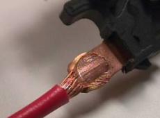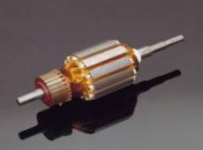
Stranded wire to Coil

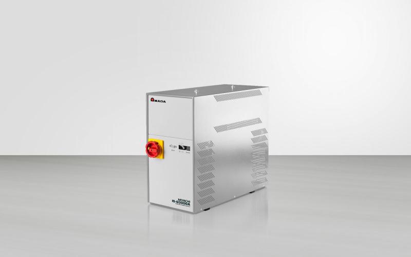
The IS-Q Series - Inverter Power Supply is designed to be used in combination with mechanical, pneumatical or motorised weld heads. It offers process control monitoring with MG3 and with the OP-AWS3-A Active Welding System. The OP-AWS3-A integrates the process control of all mechanical and electrical parameters, static and dynamic process monitoring, quality analysis with advanced SPC feature and datalogging.
| . | IS-Q3000A | IS-Q6000A | IS-Q250A | IS-Q500A |
|---|---|---|---|---|
| Performance range | 0,75 kA – 1,5 kA - 3 kA | 6 kA | 10 kA | 20 kA |
| Tipi di corrente di saldatura | Controlled DC inverter current | Controlled DC inverter current | AC or DC inverter | |
| Caratteristiche | Inverter with integrated power on button, Performance and Control Electronics, Voltage control cable und removable Display MFT1 (optional: AWS3-Display) and additional: compact version w/integrated transformer, voltage sensor cable | Inverter with integrated power on button, Performance and Control Electronics, Voltage control cable und removable Display MFT1 (optional: AWS3-Display) and additional: Compact version w/integrated transformer, voltage sensor cable | Inverter with integrated power on button, Performance and Control Electronics, Voltage control cable und removable Display MFT1 (optional: AWS3-Display) and additional: Separate DC- or AC- transformer | Inverter with integrated power on button, Performance and Control Electronics, Voltage control cable und removable Display MFT1 (optional: AWS3-Display) and additional: Separate DC- or AC- transformer, external main fuse and net filter |
| Opzioni | 19“ plug-in unit without main unit | 19“ plug-in unit ithout main unit | 19“ plug-in unit without main unit | 19“ plug-in unit without main unit |
| Controllo / modalità di controllo | Current, voltage or power feedback control, independently adjustable independently for each pulse, APC (Active Part Conditioner) function and current, voltage, performance and energy limits | Current, voltage or power feedback control, independently adjustable independently for each pulse, APC (Active Part Conditioner) function and current, voltage, performance and energy limits | Current, voltage or power feedback control, independently adjustable independently for each pulse, APC (Active Part Conditioner) function and current, voltage, performance and energy limits | Current, voltage or power feedback control, independently adjustable independently for each pulse, APC (Active Part Conditioner) function and current, voltage, performance and energy limits |
| Programmi saldatura programmabili/selezione programma di saldatura esterno | 99 at single axis; 49 per head at dual axis | 99 at single axis; 49 per head at dual axis | 99 at single axis; 49 per head at dual axis | 99 at single axis; 49 per head at dual axis |
| N. di impulsi di saldatura | 1st and/or 2nd pulse, 2nd pulse can be repeated max 10 times (decrease adjustable down to 1% of 2nd pulse) | 1st and/or 2nd pulse, 2nd pulse can be repeated max 10 times (decrease adjustable down to 1% of 2nd pulse) | 1st and/or 2nd pulse, 2nd pulse can be repeated max 10 times (decrease adjustable down to 1% of 2nd pulse) | 1st and/or 2nd pulse, 2nd pulse can be repeated max 10 times (decrease adjustable down to 1% of 2nd pulse) |
| Controllo impulso saldatura | Up slope, weld-time, down-slope, break time, impuls cycle | Up slope, weld-time, down-slope, break time, impuls cycle | Up slope, weld-time, down-slope, break time, impuls cycle | Up slope, weld-time, down-slope, break time, impuls cycle |
| Misurazione corrente | Integrated toroidal coil (Rogowski coil) | Integrated toroidal coil (Rogowski coil) | external toroidal coil | external toroidal coil |
| Misurazione tensione | Potential free, external connection (X10 axis/head 1; X11 axis/head 2) | Potential free, external connection (X10 axis/head 1; X11 axis/head 2) | Potential free, external connection (X10 axis/head 1; X11 axis/head 2) | Potential free, external connection (X10 axis/head 1; X11 axis/head 2) |
| Limit values | Display with limit exceeding upper and lower limit, time limit, welding energy limit with sensitive components (weld to limit) | Display with limit exceeding upper and lower limit, time limit, welding energy limit with sensitive components (weld to limit) | Display with limit exceeding upper and lower limit, time limit, welding energy limit with sensitive components (weld to limit) | Display with limit exceeding upper and lower limit, time limit, welding energy limit with sensitive components (weld to limit) |
| Out of limit error message | Text indication with limit and device errors; monitoring limits for U, I or P; + and – tolerance windows individually adjustable | Text indication with limit and device errors; monitoring limits for U, I or P; + and – tolerance windows individually adjustable | Text indication with limit and device errors; monitoring limits for U, I or P; + and – tolerance windows individually adjustable | Text indication with limit and device errors; monitoring limits for U, I or P; + and – tolerance windows individually adjustable |
| Parts check | Test pulse for part detection (pre-weld-check) | Test pulse for part detection (pre-weld-check) | Test pulse for part detection (pre-weld-check) | Test pulse for part detection (pre-weld-check) |
| Operazione | One button toggle wheel, monochrome display, Optional: coloured OP-AWS3-A Display, Profibus or Ethernet IP | One button toggle wheel, monochrome display, Optional: coloured OP-AWS3-A Display, Profibus or Ethernet IP | One button toggle wheel, monochrome display, Optional: coloured OP-AWS3-A Display, Profibus or Ethernet IP | One button toggle wheel, monochrome display, Optional: coloured OP-AWS3-A Display, Profibus or Ethernet IP |
| Certificazione EU | CE Compliant | CE Compliant | CE Compliant | CE Compliant |
| Continuous sound pressure level | The equivalent continuous sound pressure level rated A is below 70 dB. Sound pressure levels may vary depending on the welding material and the environmental conditions. If necessary consult an acoustic specialist. | The equivalent continuous sound pressure level rated A is below 70 dB. Sound pressure levels may vary depending on the welding material and the environmental conditions. If necessary consult an acoustic specialist. | The equivalent continuous sound pressure level rated A is below 70 dB. Sound pressure levels may vary depending on the welding material and the environmental conditions. If necessary consult an acoustic specialist. | The equivalent continuous sound pressure level rated A is below 70 dB. Sound pressure levels may vary depending on the welding material and the environmental conditions. If necessary consult an acoustic specialist. |
| Electrical data | ||||
| Tensione alimentazione | 3x 400 VAC, ± 10%, PE; 3x 230 V (optional), ISQ20-MFC 19 ± 10%, PE : non-heating, 3 pole connector | 3x 400 VAC, ± 10%, PE; 3x 230 V (optional), ± 10%, PE ISQ20-MFC 19”: non-heating, 3 pole connector | 3x 400 VAC, ± 10%, PE | 3x 400 VAC, ± 10%, PE |
| Frequenza di rete | 50 - 60 Hz | 50 - 60 Hz | 50 - 60 Hz | 50 - 60 Hz |
| Fusione | with 400 V: 3x 16 A, delayed; with 230 V (optional): 3x 32A, delayed | with 400 V: 3x 16 A, delayed; with 230 V (optional): 3x 32A, delayed | 3 x 32A, delayed | 3 x 125A, delayed (external) |
| Cavo di collegamento | with 400 V: 4 x 2.5 mm², with 230 V (optional): 4 x 4 mm² | with 400 V: 4 x 2.5 mm², with 230 V (optional): 4 x 4 mm² | 4 x 6 mm² | 4 x 50 mm² shielded |
| Classe di protezione | IP30 ISQ20-MFC 19“: depending on housing | IP30 ISQ20-MFC 19“: depending on housing | IP30 ISQ20-MFC 19“: depending on housing | IP30 ISQ20-MFC 19“: depending on housing |
| Welding transformer | internal for 3 kA | internal for 6 kA | External DC: IT-60X AC: TRM3 14-9 V MT40X-530 | External: DC: IT-113 AC: upon request |
| Power data | IS-Q3000A | IS-Q6000A | IS-Q250A | IS-Q500A |
| Connected load | 11 kVA | 11 kVA | 22 kVA | 85 kVA |
| Switching frequency | max. 20 kHz | max. 14 kHz | 1 – 10 kHz (AC) 1 – 5 kHz (DC) depending on primary current | 1 – 10 kHz (AC) 1 – 5 kHz (DC) depending on primary current |
| Frequenza uscita | 40 kHz | 26 kHz | 1 – 10 kHz (AC) 2 – 10 kHz (DC) | 1 – 10 kHz (AC) 2 – 10 kHz (DC) |
| Fundamental frequency AC | --- | --- | AC: 50 – 250 Hz | AC: 50 – 250 Hz |
| Rated power | 12 kVA | 24 kVA | 40 kVA (DC) | 25 kVA (AC), DC with IT 113: 75 kVA; dep on transformer |
| Corrente di saldatura max | 3 kA with 5% d.r. | 6 kA with 5% d.r. | 10 kA with 8% d.r. DC only | 20 kA with 15% d.r. DC only |
| Max. weld period | 320 ms/pulse | 320 ms/pulse | 640 ms/pulse | 320 ms/pulse |
| Min. weld period | 0.7 ms | 0.7 ms | DC: 0,7 ms AC: 0,5 x impuls frequency | DC: 0,7 ms AC: 0,5 x impuls frequency |
| Rated output current | 2 kA 11% d.r. | 3 kA 20% d.r. | depending on transformer | depending on transformer |
| Min. terminal voltage | 4 V with 3 kA | 4 V with 6 kA | DC: 4 V with 10 kA AC: dep on transformer | DC with IT 113: 3 V at 25 kA; AC: dep on transformer |
| Max. open-circuit voltage | 10 V | 10 V | DC: 10 V AC: dep on transformer | DC: 11 V AC: dep on transformer |
| Interfaccia | ||||
| Secondary connections | CU-rails, 2 x M8 internal thread | CU-rails, 2 x M8 internal thread | Depending on transformer | Depending on transformer |
| Ingresso analogico | Pressure sensor for proportional valve | Pressure sensor for proportional valve | Pressure sensor for proportional valve | Pressure sensor for proportional valve |
| Uscita analogica | Proportional valve control | Proportional valve control | Proportional valve control | Proportional valve control |
| Interfacce digitali | via D-Sub-9 socket; welding data output in ASCII-compatible printing format | via D-Sub-9 socket; welding data output in ASCII-compatible printing format | via D-Sub-9 socket; welding data output in ASCII-compatible printing format | via D-Sub-9 socket; welding data output in ASCII-compatible printing format |
| Ingresso interfaccia binaria | Start, quick stop, pressure switch, proximity switches, pressure sensor | Start, quick stop, pressure switch, proximity switches, pressure sensor | Start, quick stop, pressure switch, proximity switches, pressure sensor | Start, quick stop, pressure switch, proximity switches, pressure sensor |
| Uscita interfaccia binaria | a.o. stepping contact, counter, set point deviation, closing stroke, welding pressure, air valves | a.o. stepping contact, counter, set point deviation, closing stroke, welding pressure, air valves | a.o. stepping contact, counter, set point deviation, closing stroke, welding pressure, air valves | a.o. stepping contact, counter, set point deviation, closing stroke, welding pressure, air valves |
| Operazione | ||||
| Raffreddamento | Forced air ventilation, temperature controlled | Forced air ventilation, temperature controlled | Transformer water cooled | Inverter and transformer water cooled |
| Moisture | 40 - 70 %, not condensating | 40 - 70 %, not condensating | 40 - 70 %, not condensating | 40 - 70 %, not condensating |
| Ambient Temperature | 0 - 40°C | 0 - 40°C | 0 - 40°C | 0 - 40°C |
| . | IS-Q3000A | IS-Q6000A | IS-Q250A | IS-Q500A |
| Weight inverter | approx 33 kg | approx 43 kg | approx 20 kg (without transforner) | approx 31 kg (without transforner etc) |
| Dimensions inverter (BxHxW) | 216 x 420 x 480 mm 216 x 420 x 550 mm (including projection) ISQ20-MFC-19": 482 x 174 x 315 mm | 216 x 420 x 480 mm 216 x 420 x 550 mm (including projection) ISQ20-MFC-19": 482 x 174 x 315 mm | 216 x 420 x 480 mm 216 x 420 x 550 mm (including projection) ISQ20-MFC-19": 482 x 174 x 315 mm | 216 x 420 x 480 mm 216 x 420 x 550 mm (including projection) ISQ20-MFC-19": 482 x 174 x 315 mm |
| Weight transformer | --- | --- | IT-60X: approx 16 kg TRM3: approx 45 kg MT-40X-530: approx 63 kg | IT-113: approx 25,5 kg |
| Dimensions transformer (BxHxW) in mm | --- | --- | TRM3: 360 x 150 x 185 IT-60X: 284 x 110 x 170 MT-40X-530: 732 x 92 x235 | IT-113: 420 x 125 x 230 |


Inviate un campione a uno dei nostri centri tecnologici in Europa per una valutazione. Valuteremo la soluzione che soddisfa meglio le vostre esigenze. AMADA WELD TECH conduce test di fattibilità e eroga consulenza applicativa.