You are here

UB-Series - Linear DC Spot Welding Control with Built‑in Monitor (formerly known as DC29)
The UB-4000A - Linear DC Spot Welding Control with Built‑in Monitor is ideal for applications which require exceptional control, fast rise times, and high quality throughput. UB-4000A requires only single phase input power and can output up to 4000 amps. Ultra-fast rise times permit short overall weld times, resulting in less part deformation and stronger welds. This is extremely important when welding heat sensitive parts such as battery cells or sensitive electronic devices.
UB-500A provides unsurpassed levels of control for resistance micro welding. Requiring only single phase power, UB-500A is a 500 amp Linear DC control with feedback modes designed to adapt to part and process variables. This power supply should be used for smaller applications where closed-loop feedback control and fast response times are required. Safety critical applications such as those found in the medical and automotive markets will benefit from UB-500A’s precision low energy control.
Key Features UB-Series - Linear DC Spot Welding Control with Built‑in Monitor
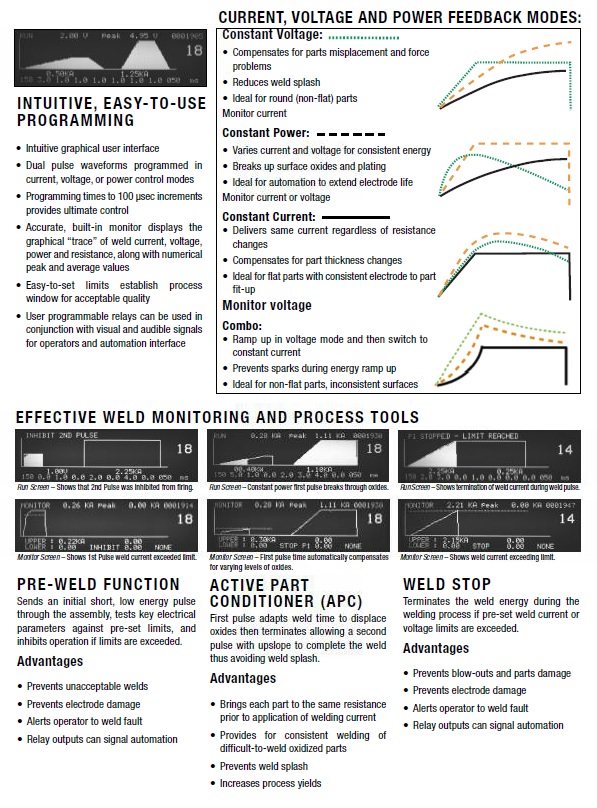
- Advanced closed-loop analog control yields repeatable and stable programmable waveforms
- Extremely fast rise times permit shorter weld times, less part deformation, longer electrode life, and greater weld strength with more part ductility
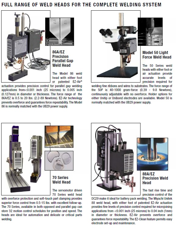
- Built-in monitor with graphical screen shows visual trace of energy over time, aiding in weld parameter optimization
- Side mounted weld cables and compact unit size increase installation options
- Single phase power input and simple I/O allows for easy setup and versatility of use
| Model number | UB-500A | UB-1500A | UB-4000A | |||
|---|---|---|---|---|---|---|
| Nominal line voltages (single phase) | 88-264 VAC 47-63 Hz | 88-264 VAC 47-63 Hz | 88-264 VAC 47-63 Hz | |||
| Repetition rate | 500 A @ 3 weld/sec for 10 ms (per weld) | 1500 A @ 1 weld/sec for 10 ms (per weld) | 4000 A @ 1 weld/sec for 10 ms (per weld) | |||
| Setting ranges: Current | 5A-500A 1 amp/step | 15A-1500A 1 amp/step | 200 A - 4000 A 10 amp/step | |||
| Setting ranges: Voltage | 0.01 V - 9.9 V 10 mV/step | 0.1 V - 9.9 V 10 mV/step | 0.1 V - 9.9 V 10 mV/step | |||
| Setting ranges: Power | 0.05 kW - 4.99 kW 10 Watt/step | 0.1 kW - 9.9kW 10 Watt/step | 0.1 kW - 25.0kW 10 Watt/step | |||
| Peak: Current | 500 A | 1500 A | 4000 A | |||
| Peak: Voltage | 10 V | 10 V | 10 V | |||
| Peak: Power | 4.9 kW | 9.9 kW | 25.0 kW | |||
| Output regulation versus line voltage variance | 2% | 2% | 2% | |||
| Output regulation versus load resistance variance | 2% | 2% | 2% | |||
| Weld period ranges | Ranges (ms) | Resolution (steps) | Ranges (ms) | Resolution (steps) | Ranges (ms) | Resolution (steps) |
| First / second pulse, up/downslope and cool periods | 0 - 99.9 | .1(0-9.9), 1(10-99) | 0 - 99.9 | .1(0-9.9), 1(10-99) | 0 - 99.9 | .1(0-9.9), 1(10-99) |
| Squeeze/hold periods | 0-999 | 1 | 0-999 | 1 | 0-999 | 1 |
| Output accuracy: Current | ±2% or 2.5 A | ±2% or 7 A | ±2% or 10 A | |||
| Output accuracy: Voltage | ±2% or 0.05 V | ±2% or 0.05 V | ±2% or 0.05 V | |||
| Output accuracy: Power | ±5% or 12 W | ±5% or 40 W | ±5% or 50 W | |||
| Features | . | |||||
| Weld heat profile control | UB-500A | UB-1500A | UB-4000A | |||
| Weld pulse control | Dial pulse with independent control of current, voltage or power on each pulse | Dial pulse with independent control of current, voltage or power on each pulse | Dial pulse with independent control of current, voltage or power on each pulse | |||
| Programmable weld pulse segments | Squeeze, upslope 1, weld 1, downslope 1, cool, upslope 2, weld 2, downslope 2, hold | Squeeze, upslope 1, weld 1, downslope 1, cool, upslope 2, weld 2, downslope 2, hold | Squeeze, upslope 1, weld 1, downslope 1, cool, upslope 2, weld 2, downslope 2, hold | |||
| Weld schedule memory | Save up to 99 different weld schedules, protected from unauthorized changes | Save up to 99 different weld schedules, protected from unauthorized changes | Save up to 99 different weld schedules, protected from unauthorized changes | |||
| Weld schedule chaining | Allows automatic linking of weld schedule sequence | Allows automatic linking of weld schedule sequence | Allows automatic linking of weld schedule sequence | |||
| Built-in weld monitor functions | ||||||
| Measurement parameters | Current, voltage, power, resistance on each pulse. | Current, voltage, power, resistance on each pulse. | Current, voltage, power, resistance on each pulse. | |||
| Graphic display | Back-lit LCD displays programmed and actual weld current, voltage, power, or resistance and upper and lower limits | Back-lit LCD displays programmed and actual weld current, voltage, power, or resistance and upper and lower limits | Back-lit LCD displays programmed and actual weld current, voltage, power, or resistance and upper and lower limits | |||
| Measurement selection | Peak or average | Peak or average | Peak or average | |||
| Current measurement range / accuracy | 0 – 500 A, ±2% of setting ±5 A | 0 – 1500 A, ±2% of setting ±10 A | 0 – 4000kA, ±2% of setting ±20 A | |||
| Voltage measurement range / accuracy | 0.1 – 9.9 V, ±2% of setting ±0.05 V | 0.01 – 9.9 V, ±2% of setting ±0.05 V | 0.01 – 9.9 V, ±2% of setting ±0.05 V | |||
| Power measurement range / accuracy | 0 – 4.9 kW, ±5% of setting ±10 W | 0 - 9.99 kV, ±2% of setting ±40 W | 0 – 25.0 kW, ±5% of setting ±50 W | |||
| Alarms | Display alert, five user programmable AC/DC relays; audio alarm | Display alert, five user programmable AC/DC relays; audio alarm | Display alert, five user programmable AC/DC relays; audio alarm | |||
| Programmable weld energy limit | Terminates weld energy when exceeding user defined current, voltage, or power limits | Terminates weld energy when exceeding user defined current, voltage, or power limits | Terminates weld energy when exceeding user defined current, voltage, or power limits | |||
| Weld pre-check | Inhibits second weld pulse when first test pulse exceeds user programmed limits | Inhibits second weld pulse when first test pulse exceeds user programmed limits | Inhibits second weld pulse when first test pulse exceeds user programmed limits | |||
| Active part conditioner | First pulse current limit in constant power | First pulse current limit in constant power | First pulse current limit in constant power | |||
| I/O and data communications | ||||||
| Input: Input Isolation | All inputs and outputs are fully isolated | All inputs and outputs are fully isolated | All inputs and outputs are fully isolated | |||
| Input: Control voltages | +24V, sourcing or sinking inputs | +24V, sourcing or sinking inputs | +24V, sourcing or sinking inputs | |||
| Input: Foot switch initiation | 1-level foot switch, 2-level foot switch | 1-level foot switch, 2-level foot switch | 1-level foot switch, 2-level foot switch | |||
| Input: Firing switch initiation | Mechanical or opto firing switch | Mechanical or opto firing switch | Mechanical or opto firing switch | |||
| Input: Remote control | Remote weld schedule select, process inhibit, emergency stop, alarm reset | Remote weld schedule select, process inhibit, emergency stop, alarm reset | Remote weld schedule select, process inhibit, emergency stop, alarm reset | |||
| Input: RS232 | Change weld schedules and individual parameters | Change weld schedules and individual parameters | Change weld schedules and individual parameters | |||
| Input: Electrode voltage | Weld voltage signal for voltage feedback operation (0 to 10V peak) | Weld voltage signal for voltage feedback operation (0 to 10V peak) | Weld voltage signal for voltage feedback operation (0 to 10V peak) | |||
| Output: Monitor | RS232 weld data out | RS232 weld data out | RS232 weld data out | |||
| Output: Weld head air valve driver | 24 VAC, 0.5 A; timing controlled by UB Series Power Supply | 24 VAC, 0.5 A; timing controlled by UB Series Power Supply | 24 VAC, 0.5 A; timing controlled by UB Series Power Supply | |||
| Output: Alarm relays | Five user-programmable opto isolated relays; programmable normally open or normally closed contacts: 30 VDC at 0.5 A Conditions: weld, end of weld, alarm, out of limits, ready, weld counter | Five user-programmable opto isolated relays; programmable normally open or normally closed contacts: 30 VDC at 0.5 A Conditions: weld, end of weld, alarm, out of limits, ready, weld counter | Five user-programmable opto isolated relays; programmable normally open or normally closed contacts: 30 VDC at 0.5 A Conditions: weld, end of weld, alarm, out of limits, ready, weld counter | |||
| Dimensions (LxWxH) | 381 mm x 213 mm x 305 mm (15 in x 8.4 in x 12 in ) | 381 mm x 213 mm x 305 mm (15 in x 8.4 in x 12 in ) | 381 mm x 213 mm x 305 mm (15 in x 8.4 in x 12 in ) | |||
| Weight | 22 kg (49 lb) | 22 kg (49 lb) | 22 kg (49 lb) |
Documentation
Battery tab to lithium ion cell
Halogen lamp filaments
Catheter guide wire assembly

Air bag detonator module (squib wire)
Customized Solutions
Send your sample to one of our technology centers in Europe for an evaluation. We will then determine which solution meets your needs best. AMADA WELD TECH offers feasibility testing and application consulting.