HF-2700A, HF-2500A - High Frequency Inverter Spot Welding Power Supply (formerly known as HF27, HF25)
The controls found on the HF-2700A, HF-2500A High Frequency Inverter Spot Welding Power Supply address the challenges of micro joining for a wide range of applications. Miniature welds are highly sensitive to small heat profile fluctuations in the resistance welding process. Overheating deforms and destroys parts, while underheating results in a weak and unacceptable bond. To achieve consistent, reliable welds of small to micro-miniature parts, heating needs to be precisely controlled. This necessitates superior control of the energy output. The HF-2700A, HF-2500A High Frequency Inverter Spot Welding Power Supply are also geared for automation featuring exceptional repetition rates, standard I/O connections and remote programming capability.
Key features HF-2700A, HF-2500A - High Frequency Inverter Spot Welding Power Supply
Control features
- Constant current, voltage, and power modes
- Monitors energy and resistance
- 2400 A maximum
- 25 kHz feedback
Weld Quality Process Tools
- Active Part Conditioning (APC)
- Pre-Weld Check
- Weld to Limits
HF-2700A Advanced Features
- Displacement and force monitoring
- Force control
- Envelope function
- Combo mod
- Energy and time limits
Specifications HF-2700A, HF-2500A - High Frequency Inverter Spot Welding Power Supply (formerly known as HF27, HF25)
| Model number | HF-2500A/240 | HF-2500A/400 | HF-2500A/480 | HF-2700A/240 | HF-2700A/400 | HF-2700A/480 |
|---|---|---|---|---|---|---|
| Nominal line voltage (3 phase) | 240 VAC | 400 VAC | 480 VAC | 240 VAC | 400 VAC | 480 VAC |
| Line voltage range (vac) | 192 to 264 | 320 to 440 | 384 to 528 | 192 to 264 | 320 to 440 | 384 to 528 |
| Input circuit rating (per phase) | 25 A | 20 A | 13 A | 25 A | 20 A | 13 A |
| Input KVA @ 3% duty cycle | 30 KVA | 30 KVA | 30 KVA | 30 KVA | 30 KVA | 30 KVA |
| Output KW @ max. demand | 12 KW | 12 KW | 12 KW | 12 KW | 12 KW | 12 KW |
| Output transformer voltage @ max. rated output current | 5.2 V | 5.2 V | 5.2 V | 5.2 V | 5.2 V | 5.2 V |
| Open circuit max. output voltage @ nominal line | 11.5 V | 11.5 V | 11.5 V | 11.5 V | 11.5 V | 11.5 V |
| Setting ranges | Current – 100 A to 2400 A; Voltage – 0.2 V to 10 V; Power – 50 W to 10 kW | Current – 100 A to 2400 A; Voltage – 0.2 V to 10 V; Power – 50 W to 10 kW | Current – 100 A to 2400 A; Voltage – 0.2 V to 10 V; Power – 50 W to 10 kW | Current – 100 A to 2400 A; Voltage – 0.2 V to 10 V; Power – 50 W to 10 kW | Current – 100 A to 2400 A; Voltage – 0.2 V to 10 V; Power – 50 W to 10 kW | Current – 100 A to 2400 A; Voltage – 0.2 V to 10 V; Power – 50 W to 10 kW |
| Output current | 2400 A @ 3% duty cycle | 2400 A @ 3% duty cycle | 2400 A @ 3% duty cycle | 2400 A @ 3% duty cycle | 2400 A @ 3% duty cycle | 2400 A @ 3% duty cycle |
| Output feedback response time (current, voltage, power) | 40 Microseconds | 40 Microseconds | 40 Microseconds | 40 Microseconds | 40 Microseconds | 40 Microseconds |
| Output regulation versus line voltage variance | 2% | 2% | 2% | 2% | 2% | 2% |
| Output regulation versus load resistance variance | 2% | 2% | 2% | 2% | 2% | 2% |
| Output repeatability current, voltage, power ± of setting | 2% | 2% | 2% | 2% | 2% | 2% |
| Weld period ranges | All segments except squeeze and hold 0.10 ms to 10 ms, 0.1 ms steps; 10 to 99 ms, 1 ms steps; squeeze and hold 0 to 999 ms, 1 ms steps | All segments except squeeze and hold 0.10 ms to 10 ms, 0.1 ms steps; 10 to 99 ms, 1 ms steps; squeeze and hold 0 to 999 ms, 1 ms steps | All segments except squeeze and hold 0.10 ms to 10 ms, 0.1 ms steps; 10 to 99 ms, 1 ms steps; squeeze and hold 0 to 999 ms, 1 ms steps | All segments except squeeze and hold 0.10 ms to 10 ms, 0.1 ms steps; 10 to 99 ms, 1 ms steps; squeeze and hold 0 to 999 ms, 1 ms steps | All segments except squeeze and hold 0.10 ms to 10 ms, 0.1 ms steps; 10 to 99 ms, 1 ms steps; squeeze and hold 0 to 999 ms, 1 ms steps | All segments except squeeze and hold 0.10 ms to 10 ms, 0.1 ms steps; 10 to 99 ms, 1 ms steps; squeeze and hold 0 to 999 ms, 1 ms steps |
| Weld energy setting accuracy | Current: 2% of setting or 2 A, whichever is greater; Voltage: 2% of setting or 0.050 V, whichever is greater; Power: 5% of setting or 20 W, whichever is greater | Current: 2% of setting or 2 A, whichever is greater; Voltage: 2% of setting or 0.050 V, whichever is greater; Power: 5% of setting or 20 W, whichever is greater | Current: 2% of setting or 2 A, whichever is greater; Voltage: 2% of setting or 0.050 V, whichever is greater; Power: 5% of setting or 20 W, whichever is greater | Current: 2% of setting or 2 A, whichever is greater; Voltage: 2% of setting or 0.050 V, whichever is greater; Power: 5% of setting or 20 W, whichever is greater | Current: 2% of setting or 2 A, whichever is greater; Voltage: 2% of setting or 0.050 V, whichever is greater; Power: 5% of setting or 20 W, whichever is greater | Current: 2% of setting or 2 A, whichever is greater; Voltage: 2% of setting or 0.050 V, whichever is greater; Power: 5% of setting or 20 W, whichever is greater |
| WELD HEAD PROFILE FUNCTIONS | ||||||
| Weld pulse control | Dual pulse with independent control of current, voltage, power or combo mode (HF27) on each pulse. | |||||
| Programmable weld pulse segments | Squeeze, upslope 1, weld 1, downslope 1, cool, upslope 2, weld 2, downslope 2, hold. | |||||
| Weld schedule memory | Save up to 100 different weld schedules, protected from unauthorized changes. | |||||
| Measurement parameters | Independent monitor of current, voltage, power, and resistance on each pulse. Envelope, time limits and energy monitor (HF27). | |||||
| Graphic display | Back-lit LCD displays programmed and actual weld current, voltage or power, upper and lower limits, and resistance. | |||||
| Measurement selection | Peak or average | |||||
| Current measurement range / accuracy | 50.0 A to 2.400 KA/±2% of reading or ±2 A, whichever is greater. | |||||
| Voltage measurement range / accuracy | 0.2 V to 9.999 V/±2% of reading or ±0.05 V, whichever is greater. | |||||
| Power measurement range / accuracy | 0.01 KW to 9.999 KW/±5% of reading or ±20 W, whichever is greater. | |||||
| Alarms | Display alert, four user programmable AC/DC relays; audio alarm. | |||||
| Programmable weld energy limit | Terminates weld energy when exceeding user defined current, voltage, or power limits. | |||||
| Weld pre-check | Inhibit second weld pulse when first test pulse exceeds user programmed limits. | |||||
| Active part conditioner | First pulse current limit in constant power allows second pulse to fire. | |||||
| I/O AND DATACOMMUNICATIONS | ||||||
| Input: Input Isolation | All inputs and outputs are fully isolated. | |||||
| Input: Control voltages | Selectable: +5 V, +24 V, sourcing or sinking inputs. | |||||
| Input: Firing switch initiation | 1-level foot switch, 2-level foot switch, mechanical or opto firing switch. | |||||
| Input: Remote control | Remote weld schedule select, process inhibit, emergency stop. | |||||
| Input: RS232 | Change weld schedules and individual parameters. | |||||
| Input: RS485 | Change weld schedules and individual weld parameters; “Daisy Chain” unit to unit, unit(s) to host computer. | |||||
| Input: Electrode voltage | Weld voltage signal for voltage feedback operation (0 to 10 V peak). | |||||
| Weld head air valve driver | 24 VAC, 1 A; timing controlled by HF-2500A/HF-2700A. Operates new EZ-Air. | |||||
| Alarm relays | Four user-programmable mechanical relays; programmable normally open or normally closed; contacts: 250 VAC at 5 A; 30 VDC at 5 A. Conditions: weld, end of weld, alarm, out of limits. | |||||
| DISPLACEMENT OPTION (HF-2700A ONLY) | ||||||
| Capabilities | Part detection, final thickness measurement, set down measurement, energy stop (weld to limit) | |||||
| Accuracy of displacement readings | ± .003 in (0.076 mm) | |||||
| Repeatability | ± 1.0 % | |||||
| Maximum travel | 1 in (25 mm) | |||||
| Alarm relays | Additional conditions: any LVDT, initial Lo/Hi, final Lo/Hi, displacement Lo/Hi, initial NG, displacement NG, energy stop | |||||
| Data output | Initial thickness, final thickness, displacement, and any alarm condition | |||||
| FORCE CONTROL AND MONITOR (HF-2700A ONLY) | ||||||
| Force input | 0 - 10 V input signal from signal conditioner or load cell | |||||
| Force measurement | End of squeeze, end of hold | |||||
| Force output | 0 - 10 V for use with proportional valve | |||||
| Force programming | lbs, kg. N. force can be stored by schedule | |||||
| WEIGHT & DIMENSIONS | ||||||
| Dimensions (LxWxH) | 460 mm x 230 mm x 325 mm (18 in x 9 in x 12.8 in) | |||||
| Weight | 25 kg (54 lb) |
Product applications HF-2700A, HF-2500A - High Frequency Inverter Spot Welding Power Supply (formerly known as HF27, HF25)
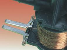 Anti-lock brake system solenoid
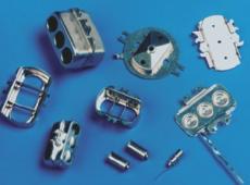 Critical parts fabrication
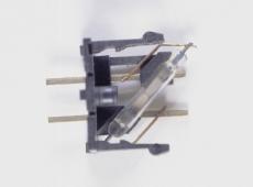 Switch assembly
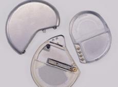 Impantable device interconnects