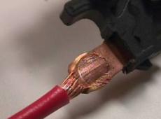
Stranded wire to Coil

The IS-Q Series - Inverter Power Supply is designed to be used in combination with mechanical, pneumatical or motorised weld heads. It offers process control monitoring with MG3 and with the OP-AWS3-A Active Welding System. The OP-AWS3-A integrates the process control of all mechanical and electrical parameters, static and dynamic process monitoring, quality analysis with advanced SPC feature and datalogging.
| . | IS-Q3000A | IS-Q6000A | IS-Q250A | IS-Q500A |
|---|---|---|---|---|
| Performance range | 0,75 kA – 1,5 kA - 3 kA | 6 kA | 10 kA | 20 kA |
| Weld current types | Controlled DC inverter current | Controlled DC inverter current | AC or DC inverter | |
| Features | Inverter with integrated power on button, Performance and Control Electronics, Voltage control cable und removable Display MFT1 (optional: AWS3-Display) and additional: compact version w/integrated transformer, voltage sensor cable | Inverter with integrated power on button, Performance and Control Electronics, Voltage control cable und removable Display MFT1 (optional: AWS3-Display) and additional: Compact version w/integrated transformer, voltage sensor cable | Inverter with integrated power on button, Performance and Control Electronics, Voltage control cable und removable Display MFT1 (optional: AWS3-Display) and additional: Separate DC- or AC- transformer | Inverter with integrated power on button, Performance and Control Electronics, Voltage control cable und removable Display MFT1 (optional: AWS3-Display) and additional: Separate DC- or AC- transformer, external main fuse and net filter |
| Options | 19“ plug-in unit without main unit | 19“ plug-in unit ithout main unit | 19“ plug-in unit without main unit | 19“ plug-in unit without main unit |
| Control / control mode | Current, voltage or power feedback control, independently adjustable independently for each pulse, APC (Active Part Conditioner) function and current, voltage, performance and energy limits | Current, voltage or power feedback control, independently adjustable independently for each pulse, APC (Active Part Conditioner) function and current, voltage, performance and energy limits | Current, voltage or power feedback control, independently adjustable independently for each pulse, APC (Active Part Conditioner) function and current, voltage, performance and energy limits | Current, voltage or power feedback control, independently adjustable independently for each pulse, APC (Active Part Conditioner) function and current, voltage, performance and energy limits |
| Programmable weld schedules / external weld schedule selection | 99 at single axis; 49 per head at dual axis | 99 at single axis; 49 per head at dual axis | 99 at single axis; 49 per head at dual axis | 99 at single axis; 49 per head at dual axis |
| # of weld pulses | 1st and/or 2nd pulse, 2nd pulse can be repeated max 10 times (decrease adjustable down to 1% of 2nd pulse) | 1st and/or 2nd pulse, 2nd pulse can be repeated max 10 times (decrease adjustable down to 1% of 2nd pulse) | 1st and/or 2nd pulse, 2nd pulse can be repeated max 10 times (decrease adjustable down to 1% of 2nd pulse) | 1st and/or 2nd pulse, 2nd pulse can be repeated max 10 times (decrease adjustable down to 1% of 2nd pulse) |
| Weld pulse control | Up slope, weld-time, down-slope, break time, impuls cycle | Up slope, weld-time, down-slope, break time, impuls cycle | Up slope, weld-time, down-slope, break time, impuls cycle | Up slope, weld-time, down-slope, break time, impuls cycle |
| Current measurement | Integrated toroidal coil (Rogowski coil) | Integrated toroidal coil (Rogowski coil) | external toroidal coil | external toroidal coil |
| Voltage measurement | Potential free, external connection (X10 axis/head 1; X11 axis/head 2) | Potential free, external connection (X10 axis/head 1; X11 axis/head 2) | Potential free, external connection (X10 axis/head 1; X11 axis/head 2) | Potential free, external connection (X10 axis/head 1; X11 axis/head 2) |
| Limit values | Display with limit exceeding upper and lower limit, time limit, welding energy limit with sensitive components (weld to limit) | Display with limit exceeding upper and lower limit, time limit, welding energy limit with sensitive components (weld to limit) | Display with limit exceeding upper and lower limit, time limit, welding energy limit with sensitive components (weld to limit) | Display with limit exceeding upper and lower limit, time limit, welding energy limit with sensitive components (weld to limit) |
| Out of limit error message | Text indication with limit and device errors; monitoring limits for U, I or P; + and – tolerance windows individually adjustable | Text indication with limit and device errors; monitoring limits for U, I or P; + and – tolerance windows individually adjustable | Text indication with limit and device errors; monitoring limits for U, I or P; + and – tolerance windows individually adjustable | Text indication with limit and device errors; monitoring limits for U, I or P; + and – tolerance windows individually adjustable |
| Parts check | Test pulse for part detection (pre-weld-check) | Test pulse for part detection (pre-weld-check) | Test pulse for part detection (pre-weld-check) | Test pulse for part detection (pre-weld-check) |
| Operation | One button toggle wheel, monochrome display, Optional: coloured OP-AWS3-A Display, Profibus or Ethernet IP | One button toggle wheel, monochrome display, Optional: coloured OP-AWS3-A Display, Profibus or Ethernet IP | One button toggle wheel, monochrome display, Optional: coloured OP-AWS3-A Display, Profibus or Ethernet IP | One button toggle wheel, monochrome display, Optional: coloured OP-AWS3-A Display, Profibus or Ethernet IP |
| EU Certification | CE Compliant | CE Compliant | CE Compliant | CE Compliant |
| Continuous sound pressure level | The equivalent continuous sound pressure level rated A is below 70 dB. Sound pressure levels may vary depending on the welding material and the environmental conditions. If necessary consult an acoustic specialist. | The equivalent continuous sound pressure level rated A is below 70 dB. Sound pressure levels may vary depending on the welding material and the environmental conditions. If necessary consult an acoustic specialist. | The equivalent continuous sound pressure level rated A is below 70 dB. Sound pressure levels may vary depending on the welding material and the environmental conditions. If necessary consult an acoustic specialist. | The equivalent continuous sound pressure level rated A is below 70 dB. Sound pressure levels may vary depending on the welding material and the environmental conditions. If necessary consult an acoustic specialist. |
| Electrical data | ||||
| Supply voltage | 3x 400 VAC, ± 10%, PE; 3x 230 V (optional), ISQ20-MFC 19 ± 10%, PE : non-heating, 3 pole connector | 3x 400 VAC, ± 10%, PE; 3x 230 V (optional), ± 10%, PE ISQ20-MFC 19”: non-heating, 3 pole connector | 3x 400 VAC, ± 10%, PE | 3x 400 VAC, ± 10%, PE |
| Mains frequency | 50 - 60 Hz | 50 - 60 Hz | 50 - 60 Hz | 50 - 60 Hz |
| Fusing | with 400 V: 3x 16 A, delayed; with 230 V (optional): 3x 32A, delayed | with 400 V: 3x 16 A, delayed; with 230 V (optional): 3x 32A, delayed | 3 x 32A, delayed | 3 x 125A, delayed (external) |
| Connecting cable | with 400 V: 4 x 2.5 mm², with 230 V (optional): 4 x 4 mm² | with 400 V: 4 x 2.5 mm², with 230 V (optional): 4 x 4 mm² | 4 x 6 mm² | 4 x 50 mm² shielded |
| Protection class | IP30 ISQ20-MFC 19“: depending on housing | IP30 ISQ20-MFC 19“: depending on housing | IP30 ISQ20-MFC 19“: depending on housing | IP30 ISQ20-MFC 19“: depending on housing |
| Welding transformer | internal for 3 kA | internal for 6 kA | External DC: IT-60X AC: TRM3 14-9 V MT40X-530 | External: DC: IT-113 AC: upon request |
| Power data | IS-Q3000A | IS-Q6000A | IS-Q250A | IS-Q500A |
| Connected load | 11 kVA | 11 kVA | 22 kVA | 85 kVA |
| Switching frequency | max. 20 kHz | max. 14 kHz | 1 – 10 kHz (AC) 1 – 5 kHz (DC) depending on primary current | 1 – 10 kHz (AC) 1 – 5 kHz (DC) depending on primary current |
| Output frequency | 40 kHz | 26 kHz | 1 – 10 kHz (AC) 2 – 10 kHz (DC) | 1 – 10 kHz (AC) 2 – 10 kHz (DC) |
| Fundamental frequency AC | --- | --- | AC: 50 – 250 Hz | AC: 50 – 250 Hz |
| Rated power | 12 kVA | 24 kVA | 40 kVA (DC) | 25 kVA (AC), DC with IT 113: 75 kVA; dep on transformer |
| Max weld current | 3 kA with 5% d.r. | 6 kA with 5% d.r. | 10 kA with 8% d.r. DC only | 20 kA with 15% d.r. DC only |
| Max. weld period | 320 ms/pulse | 320 ms/pulse | 640 ms/pulse | 320 ms/pulse |
| Min. weld period | 0.7 ms | 0.7 ms | DC: 0,7 ms AC: 0,5 x impuls frequency | DC: 0,7 ms AC: 0,5 x impuls frequency |
| Rated output current | 2 kA 11% d.r. | 3 kA 20% d.r. | depending on transformer | depending on transformer |
| Min. terminal voltage | 4 V with 3 kA | 4 V with 6 kA | DC: 4 V with 10 kA AC: dep on transformer | DC with IT 113: 3 V at 25 kA; AC: dep on transformer |
| Max. open-circuit voltage | 10 V | 10 V | DC: 10 V AC: dep on transformer | DC: 11 V AC: dep on transformer |
| Interface | ||||
| Secondary connections | CU-rails, 2 x M8 internal thread | CU-rails, 2 x M8 internal thread | Depending on transformer | Depending on transformer |
| Analog input | Pressure sensor for proportional valve | Pressure sensor for proportional valve | Pressure sensor for proportional valve | Pressure sensor for proportional valve |
| Analog output | Proportional valve control | Proportional valve control | Proportional valve control | Proportional valve control |
| Digital interfaces | via D-Sub-9 socket; welding data output in ASCII-compatible printing format | via D-Sub-9 socket; welding data output in ASCII-compatible printing format | via D-Sub-9 socket; welding data output in ASCII-compatible printing format | via D-Sub-9 socket; welding data output in ASCII-compatible printing format |
| Binary interface input | Start, quick stop, pressure switch, proximity switches, pressure sensor | Start, quick stop, pressure switch, proximity switches, pressure sensor | Start, quick stop, pressure switch, proximity switches, pressure sensor | Start, quick stop, pressure switch, proximity switches, pressure sensor |
| Binary interface output | a.o. stepping contact, counter, set point deviation, closing stroke, welding pressure, air valves | a.o. stepping contact, counter, set point deviation, closing stroke, welding pressure, air valves | a.o. stepping contact, counter, set point deviation, closing stroke, welding pressure, air valves | a.o. stepping contact, counter, set point deviation, closing stroke, welding pressure, air valves |
| Operation | ||||
| Cooling | Forced air ventilation, temperature controlled | Forced air ventilation, temperature controlled | Transformer water cooled | Inverter and transformer water cooled |
| Moisture | 40 - 70 %, not condensating | 40 - 70 %, not condensating | 40 - 70 %, not condensating | 40 - 70 %, not condensating |
| Ambient Temperature | 0 - 40°C | 0 - 40°C | 0 - 40°C | 0 - 40°C |
| . | IS-Q3000A | IS-Q6000A | IS-Q250A | IS-Q500A |
| Weight inverter | approx 33 kg | approx 43 kg | approx 20 kg (without transforner) | approx 31 kg (without transforner etc) |
| Dimensions inverter (BxHxW) | 216 x 420 x 480 mm 216 x 420 x 550 mm (including projection) ISQ20-MFC-19": 482 x 174 x 315 mm | 216 x 420 x 480 mm 216 x 420 x 550 mm (including projection) ISQ20-MFC-19": 482 x 174 x 315 mm | 216 x 420 x 480 mm 216 x 420 x 550 mm (including projection) ISQ20-MFC-19": 482 x 174 x 315 mm | 216 x 420 x 480 mm 216 x 420 x 550 mm (including projection) ISQ20-MFC-19": 482 x 174 x 315 mm |
| Weight transformer | --- | --- | IT-60X: approx 16 kg TRM3: approx 45 kg MT-40X-530: approx 63 kg | IT-113: approx 25,5 kg |
| Dimensions transformer (BxHxW) in mm | --- | --- | TRM3: 360 x 150 x 185 IT-60X: 284 x 110 x 170 MT-40X-530: 732 x 92 x235 | IT-113: 420 x 125 x 230 |
Send your sample to one of our technology centers in Europe for an evaluation. We will then determine which solution meets your needs best. AMADA WELD TECH offers feasibility testing and application consulting.